


Rocket engines appear to be remarkably simple designs. There is a combustion chamber, a converging-diverging nozzle, and, of course, fuel. But hidden within that nozzle is one of the most subtle trade-offs in rocket design: how to turn high-pressure, high-temperature gas into the greatest possible momentum while avoiding energy losses, shock waves, and nozzle deformation. The design of a rocket nozzle is a point where theoretical fluid dynamics meets real-world physics. Rocket nozzle designs have been optimized for nearly a century. Modern optimal designs do not pick one over the other; they pick both. This article will describe the physics of nozzle thrust and the evolution of techniques for designing ‘ideal’ nozzles.
Early rockets in China, India and later in Europe had fairly simple exhaust tubes. They were essentially bamboo tubes filled with gunpowder and attached to arrows. There wasn’t much understanding of optimal expansion and performance was fairly subpar.
Mysorean rockets developed under Hyder Ali and Tipu Sultan in the late 1700s were among the first to use iron casings, allowing higher internal pressures and significantly longer ranges than bamboo shoots. These are believed to have influenced European military rocket development.
Then came some breakthroughs in rocket design and fuel optimization.
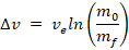
· Konstantin Tsiolkovsky (1903): He never built a rocket. He was a Russian school teacher who imagined how rockets could escape Earth’s gravity using mathematics alone. He derived the rocket equation, establishing that exhaust velocity is central to the performance of rockets.
· Robert H. Goddard (1926): Experimentally demonstrated liquid-fueled rockets. His first liquid-fuelled rocket flew only for about 2.5 seconds and reached roughly 12 metres high. Newspapers and Journalists mocked his work, but now almost all the rockets trace their origin to that one flight.
· Hermann Oberth: Advanced theoretical rocketry and inspired European development in the field. His writings became pivotal for Wernher von Braun, who later became one of the leading figures behind the V-2 and Saturn V rockets. V-2 became the first human-made object to reach space-like altitudes.
Think about placing your thumb over the end of the garden hose. The water rushes through shooting farther. It is because the opening becomes smaller and the water speeds up (A conservation of momentum application, otherwise known as the continuity principle). Similarly, nozzles when narrowed enough speed up the gas so much that the rocket can escape the atmosphere (reaches escape velocity). However, squeezing it through a narrow opening does not allow it to keep speeding up forever. At one location (throat), the gas reaches exactly the speed of sound (Mach 1) and beyond this, the gas behaves differently from ordinary airflow. This is the concept of choking the flow.
· The de Laval Nozzle (late 1880s): Gustaf de Laval developed the famous converging-diverging nozzle to accelerate steam to supersonic speeds in steam turbines.
The concept of choking the flow came into existence. It was originally invented for steam turbines.
World War II: The V-2 engine used extensively in that period incorporated converging-diverging nozzles, slight contour optimization and film cooling concepts. With the rise of supersonic aerodynamics research in the US and USSR, designers sought shorter, lighter, more efficient nozzles.
Post-war, further advances took place.
Supersonic flow does not turn and twist like subsonic flow. At normal speeds, air molecules can ‘communicate’ pressure changes in every direction. Once the flow is faster, those signals can no longer travel upstream due to inertia, not allowing them to adjust their direction the way slower flows do. They become ‘hyperbolic’.
Prandtl and Meyer developed a function to relate Mach number to the flow turning angle and govern how flow expands smoothly without shocks. They introduced expansion fans.
Earlier nozzles were all simple cones. Much of the exhaust pointed slightly sideways instead of perfectly backward, wasting thrust. Therefore, G. V. R. Rao used the Prandtl-Meyer relation along with MoC (Method of Characteristics, a specific way to solve the related partial differential equations by turning them into ordinary differential equations valid along specific curves) to introduce an optimised truncated bell contour in the 1950s. Now, almost all modern chemical rockets use Rao-optimized bell-contoured nozzles.
At the end of the day, a nozzle is judged by one fundamental question. How much thrust does it produce: FTE (Fundamental Thrust Equation) – Newton’s Third Law:

Where 

This equation reveals that the ‘optimal’ nozzle is the one that accelerates the flow to the highest possible velocity while expanding it just enough that exit pressure (

Area-Mach number relation:

Where, 


Although intimidating, this equation simply tells engineers how wide the nozzle should be at each point in order to achieve a desired gas speed. Mach number is telling us how fast the gas is with respect to the speed of sound. (Mach 2 => The gas is twice as fast as sound)
Classic designers turn to the MoC (Method of Characteristics) for designing nozzles. MoC designs are the best as they achieve 98% of ideal efficiency while being shorter and lighter, a significant advantage where every kilogram matters.
However, nowadays for nozzle design, Computational fluid dynamics (CFD) models are used, which solve the full RANS (Reynolds-Averaged-Navier-Stokes) equations, which describe the conservation relations of different entities. Softwares like OpenRocket and ANSYS also provide simulation abilities to test out and generate a rough idea of how the nozzle’s performance would be. Traditional equations treat the gas using simplified assumptions. CFD goes much further by dividing the entire nozzle into millions of tiny cells and calculating how pressure, temperature and velocity evolve inside each one.
Engineers follow a practical Workflow in designing nozzles:
· Phase 1 (Conceptual Design): Engineers rarely jump straight into simulations which are expensive. Isentropic relations and thrust equations are used to rapidly estimate chamber pressure, throat size, expansion ratio, and target performance.
· Phase 2 (Preliminary Geometry): The method of Characteristics or Rao’s optimized bell contour is used to generate an efficient nozzle shape quickly for a rough idea.
· Phase 3 (CFD Refinement): The preliminary design is simulated across multiple operating conditions. Geometry is refined to suppress separation, reduce heat loads, and improve off-design performance.
· Phase 4 (Validation): CFD results are cross-checked against classical predictions and experimental data to ensure physical consistency and then they go ahead with testing.
Traditional nozzle design tools are still invaluable. They are very fast, intuitive, and physically insightful, making them excellent for conceptual design work and teaching. But they are also very approximate, lacking the detail to capture important phenomena in the real world. CFD simulations, on the other hand, are computationally intensive and require a high level of technical sophistication, but they have the resolution to approach nozzle performance limits.
One limitation still remained. All the nozzles until then were optimised for 1 ambient pressure. When these rockets started reaching vacuum, they lost performance. Therefore, aerospike nozzles came into existence which self-adjusted to altitude through complex cooling technologies. If a traditional nozzle is like a shoe made for exactly one foot size, an aerospike nozzle is more like a flexible shoe adapting automatically. The surrounding air itself helps shape the exhaust plume.
Nowadays, SpaceX engines like Merlin and Raptor represent the latest stage of nozzle evolution apart from the countries’ respective space programs (NASA leading the way).
Higher chamber pressure ensures better exit velocity and Raptor can reach up to 30 MPa (300 times the atmospheric pressure). Other emerging technologies to look forward to are Dual-Bell Nozzles (which switch contour at altitude), full LES (Large Eddy Simulation) and DNS (Direct Numerical Simulation), and a lighter, optimized 3D-printed Lattice Cooling.
| Era | Method | Limitation | Breakthrough |
| Pre-1900 | Empirical design | No compressible flow theory | De Laval converging–diverging nozzle |
| 1940s | Conical nozzles | Divergence loss and flow non-uniformity | Supersonic expansion understanding |
| 1950s | Method of Characteristics (MoC) | Inviscid assumption | Shock-free optimized contour |
| 1960s | Rao-optimized bell nozzle | Fixed optimal altitude | Weight reduction with near-ideal performance |
| 1980s | CFD (RANS-based) | High computational cost | Shock and viscous flow modelling |
| 2020s | High chamber pressure + Additive Manufacturing + Advanced CFD | Extreme thermal and structural loads | Reusable precision optimization |
Every rocket nozzle tells the story of engineering itself. Early builders relied on intuition and experimentation. Later generations developed elegant mathematical theories that explained why nozzles worked. Today, engineers combine those same equations with supercomputers capable of simulating millions of interacting fluid particles. Yet the objective remains exactly what it was hundreds of years ago: guide a stream of hot gas so perfectly that every possible bit of energy becomes forward motion.


Leave a Reply